Short presentation
of GRAFCET, GRAFCET Elements, Rules of evolution
Repesentation of multiple sequences
Short presentation of GRAFCET
The «Sequential Function Chart», defined in the I.E.C. 848 Standard («Preparation of
function charts for control systems» International Electrotechnical Comission Publication
848) inherits from the French item GRAFCET. What is it, where does it come from, where
does it go ?
In 1975, fourty French-speaking researchers and industrial managers involved in complex
discrete system control, used to meet every two months to compare and investigate models
and methods for building sequential system control. They gathered their own experience :
seventeen techniques were then used. Some used empirical questionnaries. Other used
technological modules model. Still other used pure theoretical model derived from State
Machine or Petri Nets. They decided to build a custom model, easier than actual ones, and
more suitable to complex system and particulary manufacturing systems. After two years of
hard and laborious meetings, talks, chats, and studies, they came to propose a model
called GRAFCET. This name came from «graph» because the model had a graphic basis, and
AFCET (Association française de cybernétique économique et technique) from the
scientific association which supported the work. The basic concepts of this discrete
system model where, and remains today, quite clear and simple : the «step»,
the «action», the «transition» and the «condition
associated to transition».
GRAFCET ELEMENTS
Steps, transition and links
The STEP and the associated ACTION
The «step» represents a partial state of system, in which an action was performed
|
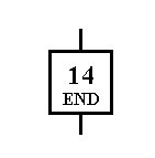
The Step is represented by a square
or a rectangle identified numericaly, the identification being in the upper part. |
|
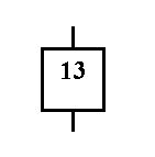
In addition to this
identification , a symbolic name may be added, representing the principal function of the
step (i.e. WAIT, END, SYNCHRONISATION etc.). |
The step can be «active» or «idle»
A Step is either active or idle and at a given moment the situation of the automated
system is entirely defined by the total set of active steps. Situation S = (X15, X100)
means the steps 15 and 100 are active
For each step are defined the actions to be carried out which are characteristic of this
situation. Such actions are only effective when the step is active
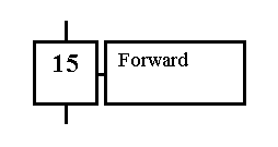
Idle step
|
It is useful to show the active steps at a
given moment by placing a reference mark in the lower part of the corresponding symbol.
|
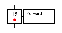 Active step Active step
|
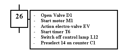
These actions to be carried out when the step is active are described literally or
symbolically within one or more rectangles of any size linked to the right hand side of
the symbol step.
| These actions may be very different in nature. |
 |
| Moreover, the carrying out of these actions may be subject to other
logical variables, as a fucntion of input variables, of internal variables or of the
active or inactive state of the other steps. |
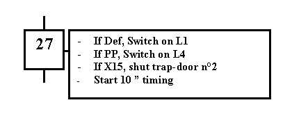 |
When step 27 is active, it is necessary to:
- turn on L1 if DEF is present
- turn on L4 if PP is absent
- shut trap door n°2 if step 15 is active (X15=1)
- start timing for ten seconds, etc...
NB. the boolean variable corresponding to the active state of step i is written xi
The associated «action» is performed when the step is active, and remains asleep when
the step is idle
The TRANSITION
The «transition» which links the previous step (one or several) of any transition and
the following step (one or several), represents the fact that the action(s) of the
previous step(s) is followed by the action(s) of the following one(s) and figures a
decision of changing system state
Nevertheless, changing is under the control of two conditions : 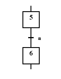
- every step previous to the transition must be active,
step 5 activated
- a boolean condition associated with the transition, must be true.
a = 1
Directed links
The Links indicate the lines of development of the state of the GRAFCET.
 The links are
horizontal or vertical
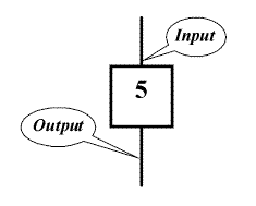 The
general direction of the description is from top to bottom. Input and output
at or from the step are represented vertically, the arrival being above. If in a few
exeptional cases the input should be below, an arrow would be mandatory.
Arrows should be used every time they facilate a better understanding and every
time the normal direction is not respected.
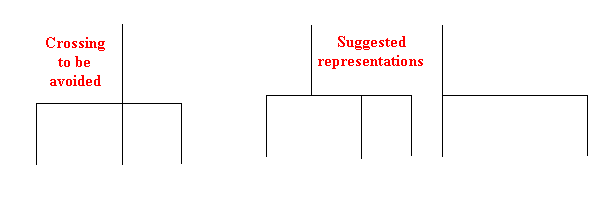
In order to avoid any ambiguity, it is preferable to avoid direct crossings of
the link lines
Rules of evolution
- Rule 1 : Initial situation
- The initial situation is characterized by the initial steps which are by definition in
the active state at the beginning of the operation.There shall be at least one initial
step.
-
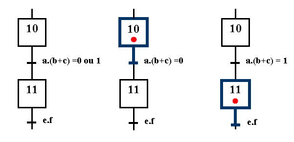
- Rule 2 : R2, Clearing of a transition
- A transition is either enabled or disabled. It is said to be enabled when all
immediately preceding steps linked to its corresponding transition symbol are active,
otherwise it is disabled. A transition cannot be cleared unless: it is enabled, and its
associated transition condition is true.
 |
| Disabled transition |
Enabled transition |
Cleared transition |
| The transition 10 -
11 is disabled, step 10 being idle |
The transition 10 -11 is still disabled, step 10 being active, but cannot
be cleared because the receptivity a.( b+ c) = 0 |
The transition is cleared because the
receptivity a.( b+ c) = 1 |
- Rule 3 : R3, Evolution of active steps
- The clearing of a transition simultaneously leads to the active state of the immediately
following step(s) and to the inactive state of the immediately preceding step(s).
 |
| Disabled transition |
Enabled transition |
Cleared transition |
| The transition is disabled, step 9 is idle |
The transition is still disable, steps 9, 13 and 22 being active, but may
not be cleared because receptivity a + b.c
= 0 |
The transition is cleared as soon as the receptivity
a + b.c = 1 |
- Rule 4 : R4, Simultaneous clearing of transitions
- All simultaneous cleared transitions are simultaneously cleared.
- Rule 5 : R5, Simultaneous activation and desactivation of a step
- If during operation, a step is simultaneously actived and deactived, priority is given
to the activation.
In 1988 it was adopted by the IEC as an international standard under the name of
«Sequential Function Chart» with reference to the number «IEC 848». Translators have
existed for many years, to implement GRAFCET on real time computers or programmable
controllers.


 Active step


 The links are
horizontal or vertical
  The
general direction of the description is from top to bottom. Input and output
at or from the step are represented vertically, the arrival being above. If in a few
exeptional cases the input should be below, an arrow would be mandatory.


