Selected symbols for fluid power systems
BS 2917 NF E 04-056


Directional control valves, control methods

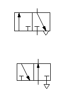
3/2-way valve 3-2.gif (1648 octets) at basic setting the supply port is closed, e. g. single-acting cylinder exhausts


at basic setting the supply port is open, e. g. single-acting cylinder ventilates
4/2-way valve 4-2.gif (1325 octets) with two flow positions and shared exhaust, e. g. for double-acting cylinder
5/2-way valve

5-2.gif (1341 octets)

with two flow postitions and separate exhausts, e. g. for double-acting cylinder
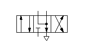
4/3-way valve

4-3.gif (1468 octets)

with floating neutral position and two positions of flow
5/3-way valve

neutral position closed 


neutral position opened


neutral position ventilated


5-3.gif (2516 octets)

with three switching positions, neutral position in the middle .The flow positions marked with double arrows mean that these valves are reversible, i.e. the flow can go in both directions.

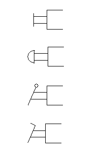
Control methods: Mechanical , Muscular, Pneumatic, Electrical

Mechanical control

Manual operation

by plunger or push-button


        by spring


        by roller


        by roller, only working in one direction (idle return)


Commande1.gif (2021 octets) general (not indicating actuation type)


        by push button


        by lever


        by pedal


Commande2.gif (1635 octets)

Pneumatic actuation


directly working due to pneumatic actuation


due to different control areas (the bigger rectangle represents the bigger control area, i.e. this area is dominant)

indirect actuation pilot actuated  due to pressure relief of pilot valve

Commande3.gif (2144 octets)


directly working due to pressure relief


indirect actuation pilot actuated  due to pneumatic actuation of pilot valve

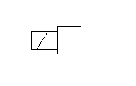
Electrical actuation

Combined actuation

by electro-magnet with a winding Commande4.gif (1201 octets) Commande5.gif (1263 octets) by electro-magnet and pilot valve